keyway
1 keyway
2 keyway
3 keyway
4 keyway
5 keyway
- шпоночная канавка
- паз для шпонки
- ориентирующий элемент электрического соединителя
ориентирующий элемент электрического соединителя
Элемент конструкции, обеспечивающий при сочленении взаимную ориентацию частей электрического соединителя
[ ГОСТ 21962-76]
EN
(mating) polarization
integral features on mating components to ensure pole-correct mating
[IEV number 581-23-25]
FR
détrompage (d’accouplement)
caractéristiques intégrées à des composants accoupables permettant d’assurer un accouplement correct de leurs pôles
[IEV number 581-23-25]
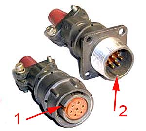
Ориентация частей электрического соединителя осуществляется с помошью ориентирующих элементов, например:
1 — паз;
2 — выступ.
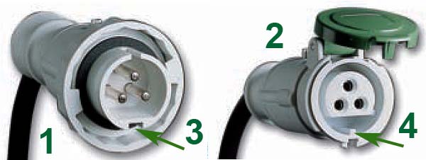
Рис. Schneider Electric
1 — кабельная вилка
2 — кабельная розетка
3 — паз
4 — выступ
Тематики
Обобщающие термины
Синонимы
- механический ключ, обеспечивающий взаимную ориентацию частей соединителя при их сочленении
Сопутствующие термины
Тематики
Синонимы
шпоночная канавка
ориентирующий паз
—
[Я.Н.Лугинский, М.С.Фези-Жилинская, Ю.С.Кабиров. Англо-русский словарь по электротехнике и электроэнергетике, Москва, 1999 г.]
Тематики
- электротехника, основные понятия
Синонимы
6 keyway
7 keyway
Англо-русский строительный словарь . Академик.ру . 2011 .
8 keyway
9 keyway
10 keyway
11 keyway
12 keyway
13 keyway
14 keyway
15 keyway
16 keyway
17 keyway
18 keyway
19 keyway
20 keyway
См. также в других словарях:
Keyway — Key way , n. See
keyway — [kē′wā΄] n. 1. a groove or slot cut in a shaft, hub, etc. to hold the key 2. the keyhole in a lock for a flat key … English World dictionary
Keyway — A keyway is the shaped channel in a lock cylinder into which the key slides to gain access to the lock tumblers.Lock keyway shapes vary widely with lock manufacturer, and many manufacturers have a number of unique profiles requiring a… … Wikipedia
keyway — n. 1. the opening in a lock or cylinder which is shaped to accept key bit or blade of a proper configuration 2. the exact cross sectional configuration of a keyway as viewed from the front. It is not necessarily the same as the key… … Locksmith dictionary
keyway — A slot cut in a shaft, pulleyhub, wheel hub, etc. A square key is placed in the slot and engages a similar keyway in the mating piece. The key prevents slippage between the two parts. Also called keyseat … Dictionary of automotive terms
keyway — noun Date: circa 1864 1. a groove or channel for a key 2. the aperture for the key in a lock having a flat metal key … New Collegiate Dictionary
keyway — /kee way /, n. 1. Mach. a groove in a shaft, the hub of a wheel, etc., for receiving part of a key holding it to another part. 2. a slot in a lock for receiving and guiding the key. 3. (in poured concrete construction) a longitudinal groove in a… … Universalium
keyway — noun A slot into which a precision attachment (a key) is fitted … Wiktionary
keyway — The female portion of a precision attachment. * * * key·way (keґwa) the slot into which the male portion of a precision attachment fits … Medical dictionary
keyway — n. slot or channel for a key; keyhole of a cylinder lock … English contemporary dictionary
keyway — noun a slot cut in a part of a machine or an electrical connector, to ensure correct orientation with another part which is fitted with a key … English new terms dictionary
Источник
Keys and Keyways
What are Keys & keyways?
A key and the keyways make up a Keyed joint to secure the hub and the shaft to prevent relative movement between a power transmitting shaft and an attached component. For example, Gear drives, Pulleys or Sprockets are connected securely using keys to the power transmitting shaft (Figure 1).
Keyed joints are an important part of mechanical power transmission elements shaft and couplings, where it ensures the connection transmits the load, power & rotation without slipping and within the accuracy requirement of the design.
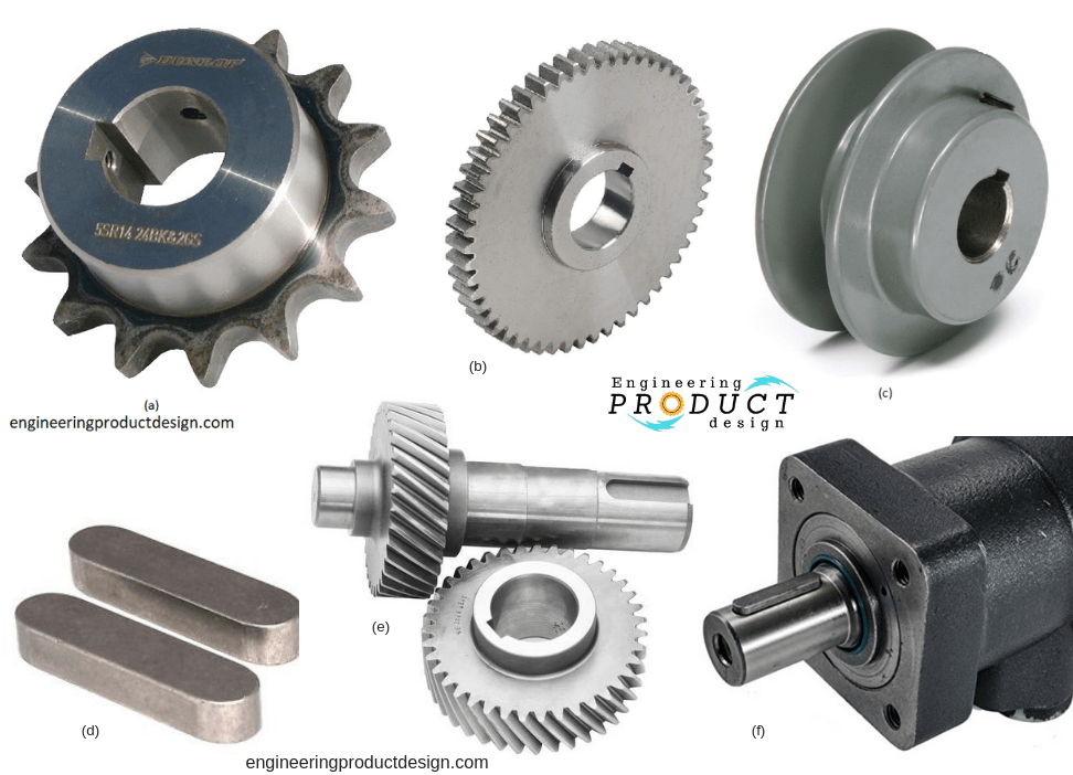 Figure 1. Shaft keys & keyways examples ( source: google images/IndiaMART)
A key is usually made from steel and is inserted or mounted between the shaft and the hub of the component in an axial direction to prevent relative movement. Keyseat is a recess in the shaft and the Keyway is the recess in the hub to receive the key and thus securely lock the component. Generally, the term keyseat is rarely used as keyway is referred to both recesses in the industry (Figure 2).
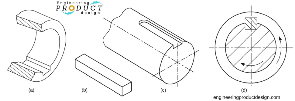 Figure 2. a – Keyway, b – key, c – keyseat, d – keyed joint (Simmons & Maguire, 2004)
Shaft and hub keyways are often cut on key seating machines but can also be made using broaching, milling, shaping, slotting EDM.
Retention elements such as Splines, flexible couplings, tapered joints etc are also used. If it’s a very low power transmission, set screws and pins can be used as well. If the set screws or in some cases of keyed joints are to be used, there must be a method of axial constraints such as circlips and retaining rings.
Advantages & limits of keyed joints
There are various advantages and disadvantages of using shaft keys hence proper consideration must be given to the finer details of the overall design to evaluate the suitability of the keyed joint.
Advantages of shaft keys & keyed joint
- Cheap manufacturing cost
- Well standardised ( ISO, BS, DIN and ANSI)
- Medium to High torque transmission
- Easy mount and dismount, hence easily reusable
Disadvantages of shaft keys & keyed joint
- Not suitable for alternating directional loads and shocks
- Possible axial displacement of hub unless locked by an extra component such as a set screw or Circlip
- Over time keyed joint might become very difficult to dismantle
- Keyways introduce stress point due to notch effect and reduce shaft strength
- Introduces shaft imbalance
- Difficult to calculate and combine the load-carrying and the tolerance stack analysis hence keyed joints are over-dimensioned
- To transmit axial force, it needs a stop lock
Types of Keys
Shaft keys come in a wide variety of types and shapes and can be divided into the following four categories along with the subcategories. (Figure 3)
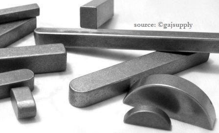 Figure 3. Types of Keys for shaft Keys ( source: gajsupply)
- Sunk Keys
- Rectangular & square keys
- Parallel keys
- Gib head keys
- Feather key (sliding clearance with keys)
- Woodruff key
- Saddle keys
- Flat & Hollow saddle keys
- Tangent keys
- Round/Circular keys
Of the above types of keys, the Parallel square key and woodruff key are probably used more widely than others due to ease of use and cost.
Double key – Because of manufacturing tolerances and to avoid double fits, only one parallel key is used, but Double keys are occasionally used for very high infrequent loads. This should only be considered if the material is ductile. For these, the calculations should be based on one and a half parallel key.
Sunk Keys
Sunk keys are sunk into the shaft for half its thickness, where the measurement is taken at the side of the key. Not along the centre line through the shaft. (Figure 4 & 5)
Rectangular/square keys
Rectangular keys as shown are wider than their height and sometimes called a flat key. These are used on shafts up to about 500 mm or 20″ in diameter. The extra key width allows it to transmit greater torque without increasing the depth. An increase in depth means a weaker shaft due to a reduction in effective shaft cross-sectional area.
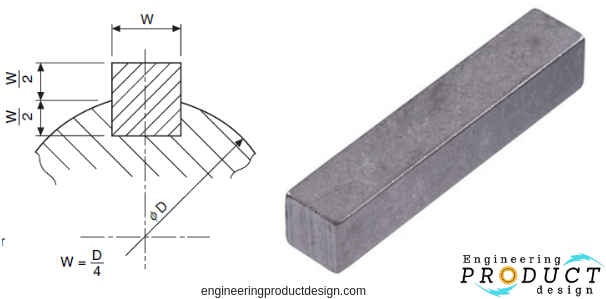 Figure 5. Square shaft key (Simmons & Maguire, 2004, Google images)
Square keys as their names suggest are square cross-sectional keys and generally specified for shafts up to about 25mm or 1″. They can be used for larger shafts when deeper key depth is desirable compared to rectangular keys. An increase in depth means a weaker shaft due to the reduction in effective shaft cross-sectional area.
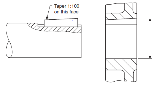 Figure 6. Shaft key taper (Simmons & Maguire, 2004)
Square and rectangular keys may have a taper of 1 in 100 along the length of the key as shown in figure 6.
Parallel sunk keys
Parallel sunk keys can be either rectangular or square section but without the taper. These keys are inexpensive and readily available. It is one of the easiest to install. But the keys need to be ideally held by a set screw through the hub. Because vibration or rotational direction reversal often push the key out.
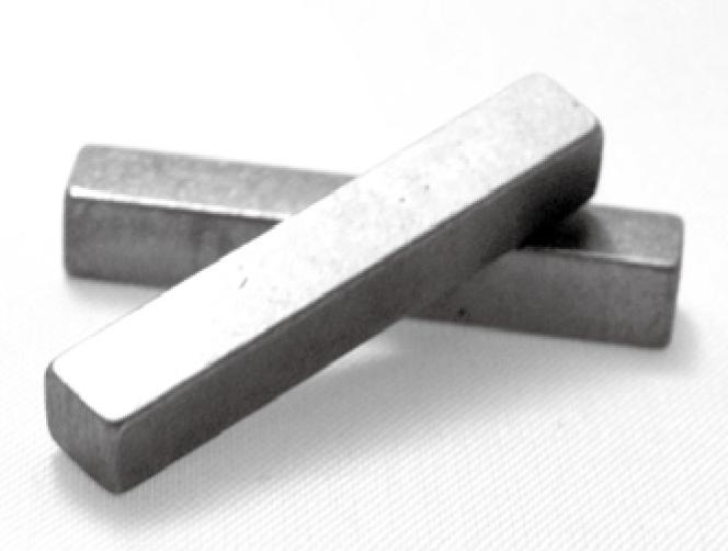 Figure 7. parallel shaft key (machinekeystock.com)
These keys are generally fitted tightly to the bottom of the shaft keyway and the sides of the keyed joint, leaving a clearance at the top of the hub keyway.
Gib head sunk keys
A Gib head-on sunk keys are added to make it easier to remove. As shown in figure 8, Gib head sunk keys are generally rectangular or square keys with a taper on the top surface to ensure a tight fit.
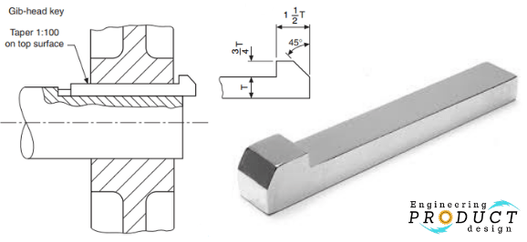 Figure 8. Gib head key (Simmons & Maguire, 2004)
Feather keys
Feather keys are attached to either the shaft or the hub to permit relative axial movement. As shown in the picture there are three main feather keys. Double-headed, Peg feather and Feather key. This enables power transmission between the shaft and hub with its parallel opposite faces, at the same time allowing it to slide.
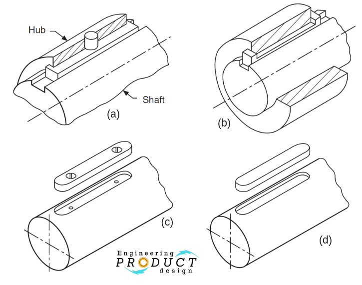 Figure 9. a – Peg feather key, b – Double-headed, c – feather key with fixing, d – standard Feather key (Simmons & Maguire, 2004)
Woodruff keys
The Woodruff key is a semi-circular disc and fits into a circular recess in the shaft which is machined by a woodruff keyway cutter. These woodruff keys are mostly used in machine tools and automobile shafts from ¼” to 2½” (6 mm to 60 mm) in diameter. Woodruff keys are not capable of carrying the same load as the long parallel keys.
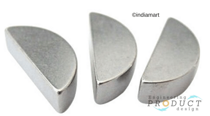 Figure 10 Woodruff keys ( source: IndiaMART)
The advantages of the Woodruff key is that it is capable of accommodating any taper in the hub keyway, its captive and the depth prevents the key from turning over.
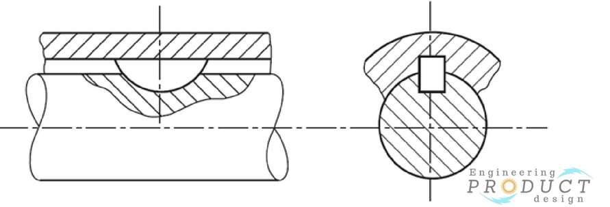 Figure 11. Woodruff key and keyway (Simmons & Maguire, 2004)
The disadvantages or drawbacks of woodruff keys are that the depth of the keyway weaken the shaft, these cannot be used as a feather key, difficult to install and short and can’t carry too much load
Saddle keys
Compared to sunk keys, saddle keys are not sunk into the shaft and hub instead they are only sunk into the hub. They either sit on a flat or circumference of the shaft. Power transmission is achieved through friction between the shaft and the key. As shown in the below figure, Saddle keys can be subdivided into Flat saddle and Hollow saddle keys and are only suitable for light loads to avoid slipping along the shaft.
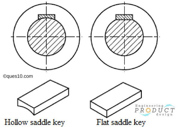 Figure 12. Types of Saddle keys (source:ques.com)
A flat saddle key is tapered at the top and flat at the bottom as shown in figure 13. The key fits into a tapered hub keyway pushing down on the flat face of the shaft
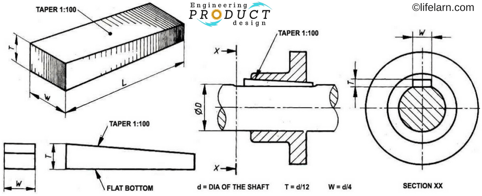 Figure 13. Flat saddle key engagement ( source: lifelarn)
A hollow saddle key is tapered at the top and curved at the bottom as shown in figure 14. The key fits into a tapered hub keyway and pushed down on the curved circumferential surface of the shaft.
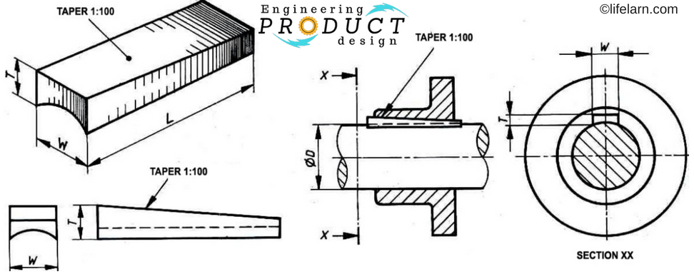 Figure 14. Hollow saddle key engagement (source:lifelarn)
Tangent keys
The tangent keys or sometimes called Tangential keys are fitted as a pair at right angles as shown in figure 15, where each key withstands torsion in one direction only. These are used in large heavy-duty shafts.
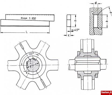 Figure 15. Tangential Keys and Tangential Keyways ( source: fasten.it)
Round / Circular Keys
The round keys are circular in section and fit into holes drilled partly in the shaft and partly in the hub. They have the advantage of easy manufacturing as their keyways may be drilled and reamed after the mating parts have been assembled. Round keys are usually considered to be most appropriate for low power drives.
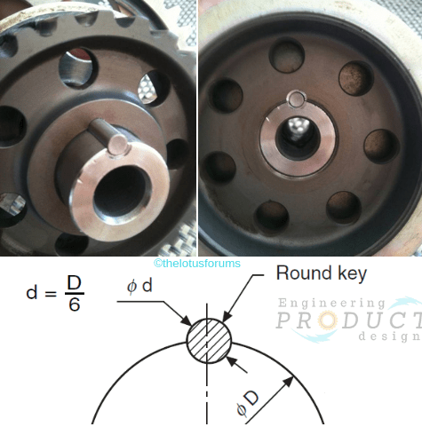 Figure 16. Circular key and keyway
Keyway design and key sizing
Shaft key selection is crucial in avoiding premature failure on keyed joints. Read “Shaft key selection & shaft keyway design guide” to understand how to calculate both shear and compressive stresses on shaft key. The article also discusses critical factors such as key material, load type, correct fit etc to consider during the embodiment design of the keyed joint.
Standards & Specification
Refer to tabulated dimensions and tolerances of metric keyways for parallel keys and woodruff keys as per BS 4235-1:1972. Along with keyway size tolerances and keyway depth sizes, some standards also provide information on the recommended key size, keyway depth as a function of shaft diameter
- Recommendations for key size, length and keyway depth as a function of shaft diameter are provided in ASME Standards B17.1-1967, ASME standard B17.2-1967
- Specification for metric keys and keyways – Parallel and taper keys BS 4235-1:1972
- Matching woodruff key to shaft diameter is also specified in DIN 6888
- Tangential Keys and Tangential Keyways for alternating shock loads specification DIN 268:1974
- Tangential Keys and Tangential Keyways for constant loads specification DIN 271:1974
Источник